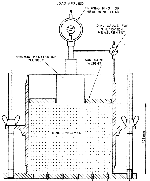
Expansion Ratio - The expansion ratio based on tests conducted as specified in 5.1 shall be calculated as follws:
where,
-
df = final dial gauge reading in mm,
-
d, = initial dial gauge reading in mm,
-
h = initial height of the specimen in mm.
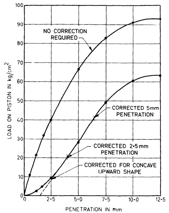
Load Penetration Curve - The load penetration curve shall be plotted (see Fig. 2) This curve will be mainly convex upwards although the initial portion of the curve may be concave upwards due to surface irregularities. A correction shall then be applied by drawing a tangent to the upper curve at the point of contraflexure. The corrected curve shall be taken to be this tangent plus the convex portion af the original curve with the origin of strains shifted to the point where the tangent cuts the horizontal strain axis as illustrated in Fig. 2.
Bearing Ratio - Corresponding to the penetration value at which the California bearing ratio is desired, corrected load value shall be taken from the load penetration curve and the California bearing ratio calculated as follows:
where,
-
PT = corrected unit (or total) test load corresponding to the chosen penetration from the load penetration curve
-
PS = unit (or total) standard load fo’r the same depth of penetration as for P, taken from Table 1.
The CBR vlues are usually calculated for penetration of 2.5 mm and 5 mm. Generally, the CBR value at 2.5 mm penetration will be greater than that at 4 mm penetration and in such a case the former shall be taken as the CBR value for design purposes.

Fig.1 Setup for cbr test

Fig.2 Correction load penetration curves
If the CBR value corresponding to a penetration of 5 mm exceeds that for 2.5 mm, the test shall be repeated. If identical results follow, the bearing ratio corresponding to 5 mm penetration shall be taken for design.
| Penetration depth (1) mm |
Unit standard load (2) kgf/cm2 |
Total standard load (3) kgf |
| 2.5 |
70 |
1370 |
| 5.0 |
105 |
2055 |
| 7.5 |
134 |
2630 |
| 10.5 |
162 |
3180 |
| 12.5 |
183 |
3600 |